6 Writing and Optimizing ARM Assembly Code
C 코드 수준에서 최적화가 불가능한 영역에서, 다음과 같은 세 가지 어셈블리 코드 레벨의 최적화 기법을 적용할 수 있다.
| (1) | instruction scheduling |
| (2) | register allocation |
| (3) | conditional execution |
어셈블러는 ARM macro assembler인 armasm을 사용한다.
Thumb mode는 이번 chapter에서 다루지 않는다.
6.1 Writing Assembly Code
ARM 어셈블리 코드를 익히기 위해, 먼저 예시를 통해 C 코드를 어셈블리 코드로 변환해 보자.
6.1.1 Convert C Function to Assembly Function
다음은 0~9까지 모든 정수의 제곱 값을 출력하는 square() 함수이다. C로 구현한 함수를 어셈블리 코드로 대체할 것이다.
C 코드 내부에서는 함수의 선언만 남겨둔 채, armasm 어셈블리 파일(square.s)과 연결한다.
| C code | Assembly | Assembly(Thumb mode) |
|
|
|
directive는 다음 의미를 갖는다.
AREA코드가 live in하는 섹션 정의 EXPORTexternal linking 수행
컴파일은 다음 명령으로 수행할 수 있다.armcc -c main1.c armasm square.s armlink -o main1.axf main1.o square.o
6.1.2 Call Subroutine from Assembly Routine
다음 예시를 통해, 어셈블리 루틴 내부에서 서브루틴을 호출하는 방법을 살펴보자. (어셈블리 코드에서 C 라이브러리 루틴 printf를 호출할 것이다.)
printf서브루틴 호출 시, 기존 루틴에서도 사용한r4(i),lr레지스터를 보존해야 한다.
| Assembly | Assembly(Thumb mode) |
|
|
symbol, specifier, directive는 다음과 같은 의미를 갖는다.
Lib$$Request$$armlibsymbol링커가 표준 ARM C 라이브러리와 링크하도록 요청 WEAKspecifier링커에게 심볼을 찾지 못할 경우 무시하도록 요청 (대신 0 값을 사용) RNdirective레지스터 이름을 지정 (앞서, r4대신i사용)DCBdirectivebyte data 정의
6.1.3 Pass More than Four Parameters
다음 예시는 여러 개의 인자를 전달 받는 함수(sumof())이다.
-
N: 리스트에서 합산을 수행할 값의 개수 -
처음 세 값은 레지스터
r1-r3에 위치하며, 나머지 값은 스택에 위치한다.
| C code | Assembly |
|
|
6.2 Profiling And Cycle Counting
프로파일러(profiler)란, 각 서브루틴에 소요되는 latency 혹은 #cycles을 측정하는 도구이다.
-
이를 활용하여 코드에서 가장 중요한 루틴(즉, 최적화할 루틴)을 식별할 수 있다.
-
cycle-counting hardware: 특정 루틴의 수행에 필요한 cycle 수를 측정한다.
6.3 Instruction Scheduling
ARM은 단계별 pipelining을 통해 여러 명령을 병렬로 수행한다. 다음은 ARM의 대표적인 명령어가 파이프라인 내부에서 실행되는 데 필요한 #cycle를 정리한 표이다.
가정: zero-wait-state memory for an uncached system, or a cache hit for a cached system
| instructions | #cycles | note |
|---|---|---|
| ALU operations (addition, subtraction, logical) |
1 | |
| 32-bit Load instructions (e.g., 개 32-bit word 로드( LDR, LDM)) |
- 마지막에 적재한 값은 바로 다음 1 cycle 동안 사용 불가 - single value LDM 명령은 예외적으로 2 cycle 소요- 명령어에서 pc를 로드하는 경우, 2 cycle 추가 소요 |
|
| 16-bit or 8-bit Load instructions ( LDR, LDRSB, LDRH, LDRSH) |
1 | - 적재한 값은 다음 2 cycle 동안 사용 불가 |
| Branch instruction | 3 | |
| Store instruction | - single value STM 명령은, 예외적으로 2 cycle 소요 |
|
| Multiply instructions | varying | - 2번째 operand에 따라 #cycle 좌우 |
6.3.1 ARM9TDMI Pipeline
다음은 ARM9TDMI 프로세서의 5개 pipeline stage이다.
-
LS1 단계: load/store 명령만 해당
-
LS2 단계: 8-bit 혹은 16-bit halfward load 명령만 해당
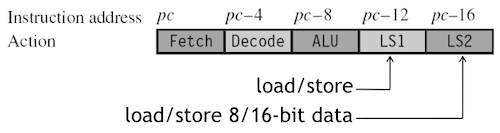
| stage | description | note |
|---|---|---|
| (1) Fetch | pc가 가리키는 명령을 fetch |
|
| (2) Decode | 직전 cycle에서 fetch한 명령을 decode | - data hazard를 방지하기 위한 forwarding(bypassing)이 없을 경우, register bank에서 input operands를 읽는다. |
| (3) ALU | 직전 cycle에서 decode한 명령어를 execute |
- 일반적으로 data processing operation에서 필요한 연산이나, load, store, branch operation에 필요한 address 연산을 수행한다. - Execute하는 명령은 pc-8(Thumb state의 경우 pc-4) 주소에 대응된다.- 일부 명령은 ALU에서 여러 사이클을 소비한다.(e.g., multiply and register-controlled shift operation) |
| (4) LS1 | 데이터를 load 혹은 store | |
| (5) LS2 | byte 혹은 halfword load instruction에서 데이터 추출 후, zero(or signed) extend |
파이프라인 5단계를 완료하면 결과는 레지스터 파일에 기록되며,
pc는 'fetch'할 명령어 주소를 가리키게 된다.
6.3.2 Pipeline Hazard
현재 명령어에서 연산이 끝나지 않은 이전 명령어 결과가 필요한 경우, 파이프라인이 멈추는 pipeline hazard(pipeline interlock) 문제가 발생한다. 다음 예시를 살펴보자.
| Example 1: no interlock (total 2 cycles) | |
| Assembly | Description |
|
| cycle | | | | --- | --- | --- | | 1 | (ALU) `r0 = r0 + r1` 계산 | | | 2 | (ALU) 앞선 결과를 사용해 `r0 = r0 + r2` 계산 | | |
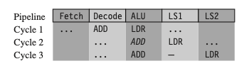
다음은 LDR 명령어를 포함한 파이프라인의 동작 예시다.
| Example 2: one-cycle interlock caused by load use (total 3 cycles) | |
| Assembly | Description |
|
| cycle | | | | --- | --- | --- | | 1 | (ALU) `ADD` 명령을 병렬로 decode하면서, `LDR` 명령의 주소 `r2 + 4`를 계산 | | | 2 | `LDR` 명령에서 아직 `r1` 값을 로드하지 않았으므로 `ADD` 명령 진행 불가 | **(stall 발생)** | | 3 | `r1`이 준비된 세 번째 cycle에서, ALU가 `ADD` 명령을 실행 | | |
프로세서는 로드 명령이 LS1 단계를 완료하는 동안, 파이프라인의 ALU 단계에서 한 사이클 동안
ADD실행을 중단한다(이탤릭체 ADD로 표시된 부분)
LDR명령은 파이프라인을 따라 진행되지만ADD명령은 멈춰 있기 때문에 두 명령 사이에 간격이 생긴다. 이 간격을 pipeline bubble이라고 부른다.
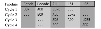
다음은 byte load instruction인 LDRB를 포함한 파이프라인의 동작 예시다.
| Example 3: one-cycle interlock caused by delayed load use (total 4 cycles) | |
| Assembly | Description |
|
| cycle | | |
| --- | --- | --- |
| 1 | (ALU) `ADD` 명령을 병렬로 decode하면서, `LDRB` 명령의 주소 `r2 + 1`를 계산 | |
| 2 | `ADD` 명령 수행 (해당 `ADD` 명령은 `r1`을 사용하지 않으므로, 어떤 stall도 일으키지 않는다.) | | | 3 | `LDRB` 명령에서 아직 `r1` 값을 로드하지 않았으므로(LS2 단계 미완료) `EOR` 명령 진행 불가 | **(stall 발생)** | | 4 | `r1`이 준비된 4 번째 cycle에서, ALU가 `EOR` 명령을 실행 | | |
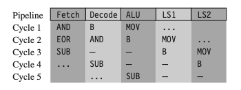
다음은 분기 명령어 B를 포함한 파이프라인의 동작 예시다. 분기 명령어에 3 cycle이 필요한 이유를 다음 예시를 통해 살펴보자.
- 새로운 주소로 jump할 때, 파이프라인을 flush해야 한다. (리필: 2 cycle 소요)
| Example 4: branch instructions (total 5 cycles) | |
| Assembly | Description |
|
| cycle | | | | --- | --- | --- | | 1 | `MOV` 명령어 실행 | | | 2 | 분기 명령어는 target address를 계산 | **(분기에 의해 stall 발생)** | | 3 | 파이프라인을 플러시하고 새로운 PC 값에 따라 파이프라인을 다시 채운다 | **(stall)** | | 4 | - | | | 5 | `SUB` 명령이 정상적으로 실행된다. | | |
6.3.3 Scheduling of Load Instructions
컴파일러 수준에서는 Aliasing 문제로 인해 최적화가 제한된다. (5.6절 참조) - 컴파일러는 두 포인터가 동일한 주소를 가리키지 않는 것이 확실하지 않으면, load를 save보다 앞으로 이동시킬 수 없기 때문이다.
다음은 0으로 끝나는 입력 문자열 *in를 읽어와서, 출력 문자열 *out에 소문자로 변환하여 저장하는 str_tolower() 함수이다. 두 가지 대표적인 최적화 기법(preloading, unrolling)을 적용할 것이다.
| Optimization | Description |
|---|---|
| preloading | 이전 루프의 종료 시점에서, 루프에 필요한 데이터를 미리 load한다. |
| unrolling | 루프의 본문을 (i, i + 1, i + 2처럼) 언롤링하여 수행한다. |
| C code | Assembly |
|
|
load instruction은 전체 명령어의 약 1/3을 차지할 수준으로 빈번하게 사용된다.
6.3.3.1 Load Scheduling by Preloading
preloading을 사용하면, 코드 크기를 거의 늘리지 않고 load scheduling을 개선할 수 있다. 특히 ARM 아키텍처의 조건부 명령어를 활용하면 효율적으로 구현할 수 있다.
단, 첫 번째와 마지막 루프에서 예외적인 처리가 필요하다. (루프 i에서 루프 i + 1의 데이터를 로드하는 특성 때문)
| loop | description |
|---|---|
| 1st loop | 루프가 시작되기 전에 load 명령어를 추가하여 데이터를 preload. (str_tolower_preload) |
| last loop | 루프에서 데이터를 읽지 않아야 한다. (배열의 끝을 넘어서 읽는 문제 발생) |
다음 코드(preload 적용 예제)의 마지막 루프에서는 byte load를 수행하지 않는다.
out     RN 0                      ; pointer to output string
in      RN 1                      ; pointer to input string
c       RN 2                      ; character loaded
t       RN 3                      ; scratch register

        ; void str_tolower_preload(char *out, char *in)
str_tolower_preload
        LDRB    c, [in], #1       ; c = *(in++)
loop
        SUB     t, c, #'A'        ; t = c-'A'
        CMP     t, #'Z'-'A'       ; if (t <= 'Z'-'A')
        ADDLS   c, c, #'a'-'A'    ;   c += 'a'-'A';
        STRB    c, [out], #1      ; *(out++) = (char)c;
        TEQ     c, #0             ; test if c==0
        LDRNEB  c, [in], #1       ; if (c!=0) { c=*in++;
        BNE     loop              ;             goto loop; }
        MOV     pc, lr            ; return
6.3.3.2 Load Scheduling by Unrolling
unrolling을 통해, 루프 i의 결과가 준비되지 않아도, 루프 i + 1 작업을 수행한다. (적용하지 않으면, loop i + 1에서 i의 결과를 기다려야 한다.)
out     RN 0                      ; pointer to output string
in      RN 1                      ; pointer to input string
ca0     RN 2                      ; character 0
t       RN 3                      ; scratch register
ca1     RN 12                     ; character 1
ca2     RN 14                     ; character 2

        ; void str_tolower_unrolled(char *out, char *in)
str_tolower_unrolled
        STMFD   sp!, {lr}         ; function entry
loop_next3
        LDRB    ca0, [in], #1     ; ca0 = *in++;
        LDRB    ca1, [in], #1     ; ca1 = *in++;
        LDRB    ca2, [in], #1     ; ca2 = *in++;
        SUB     t, ca0, #'A'      ; convert ca0 to lower case
        CMP     t, #'Z'-'A'
        ADDLS   ca0, ca0, #'a'-'A'
        SUB     t, ca1, #'A'      ; convert ca1 to lower case
        CMP     t, #'Z'-'A'
        ADDLS   ca1, ca1, #'a'-'A'
        SUB     t, ca2, #'A'      ; convert ca2 to lower case
        CMP     t, #'Z'-'A'
        ADDLS   ca2, ca2, #'a'-'A'
        STRB    ca0, [out], #1    ; *out++ = ca0;
        TEQ     ca0, #0           ; if (ca0!=0)
        STRNEB  ca1, [out], #1    ;   *out++ = ca1;
        TEQNE   ca1, #0           ; if (ca0!=0 && ca1!=0)
        STRNEB  ca2, [out], #1    ;   *out++ = ca2;
        TEQNE   ca2, #0           ; if (ca0!=0 && ca1!=0 && ca2!=0)
        BNE     loop_next3        ;   goto loop_next3;
        LDMFD   sp!, {pc}         ; return;